Baseband Signals and Carrier Upconversion
Through the modulation schemes introduced in the preceding sections, we can convert the data to be transmitted into a signal—typically a low-frequency signal known as the baseband signal. Although baseband signals can, in principle, be transmitted directly for communication, such low-frequency signals are rarely used in practice. For example, Wi-Fi operates at 2.4 GHz. Intuitively, therefore, a modulated baseband signal is first “shifted” to a higher frequency before transmission. This process is generally referred to in communications as carrier upconversion (or simply upconversion), i.e., modulating the baseband signal onto a high-frequency carrier signal, followed by transmission. This approach is adopted for the following reasons:
-
Modulating baseband signals onto carrier signals of different frequencies prevents mutual interference among multiple signals.
-
Higher-frequency carrier signals have shorter wavelengths. In wireless communication, achieving high radiation efficiency requires antenna dimensions comparable to the wavelength of the transmitted signal; thus, shorter wavelengths (i.e., higher frequencies) enable smaller antennas.
-
Governments worldwide regulate electromagnetic spectrum usage, allocating certain frequency bands for military use and others for commercial use. Common applications such as Wi-Fi, Bluetooth, and AM/FM radio operate exclusively within designated commercial bands. For instance, the 2.4 GHz band (2.4–2.5 GHz) is a globally accepted unlicensed industrial, scientific, and medical (ISM) band. Transmitting signals in unauthorized bands constitutes illegal interference with legitimate communications.
The carrier signal is typically a single-frequency sinusoid. If the carrier frequency is \(f_c\), then the carrier signal is \(A_csin(2\pi f_ct)\), where \(A_c\) denotes the amplitude of the carrier signal. During modulation, the baseband signal \(B(t)\) must be modulated onto this carrier.
Consider how to shift the baseband signal to the carrier frequency.
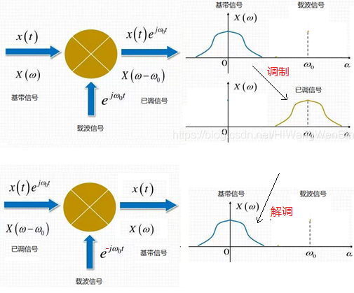
Intuitively, upconversion can be achieved by multiplying the baseband signal with the carrier signal, yielding the modulated signal \(M(t)=B(t)A_csin(2\pi f_ct)\). Since the baseband signal \(B(t)\) has relatively low frequency, the resulting modulated signal \(M(t)\) is centered near the carrier frequency \(f_c\).
The figure below illustrates the spectral shifting involved in both upconversion (modulation) and downconversion (demodulation).
How does the receiver decode the received signal?
Upon receiving the signal, the receiver’s first task is to shift the signal frequency back down from the carrier frequency to recover the baseband signal—i.e., perform downconversion—and subsequently reconstruct the original transmitted data according to the modulation scheme. Only then can further processing occur. In most experimental setups, the signals accessible from hardware devices are baseband signals—that is, already downconverted—while upconverted (RF) signals are generally inaccessible.
The general downconversion process is: \(B'(t) = M(t) \times sin(2\pi f_ct)\). You may compute the result of this operation and verify how the original baseband signal $ M(t) $ is recovered.
\(B'(t) = M(t) \times sin(2\pi f_ct) = B(t)sin^2(2\pi f_ct) = B(t)\frac{1}{2}(1- cos(4\pi f_ct))\). Consider how to extract \(B(t)\) from this result.
In our experiments, acoustic signals are used to simulate wireless communication. Because acoustic signals typically occupy low frequencies, many of the example code listings in this chapter—designed for acoustic transmission—employ carrier upconversion, while others transmit the baseband signal directly without upconversion.